Jetty's Wifi Web Based Laminar Jet Project
Page 1 of 2 • 1, 2 ![]()

Re: Cutter Design
![]() jetty Wed Sep 28, 2011 9:49 am
jetty Wed Sep 28, 2011 9:49 am
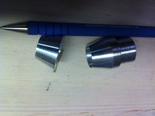
This shows the conical inserts to the quick change nozzle to reduce contamination of the stream on the cut.
The one on the right is the nozzle insert. The one on the left I use on clear top plate of the cutter after the stream has been cut, ideally this was designed to be on the underside of the top plate, not on the top side as you see it in the picture of the cutter.
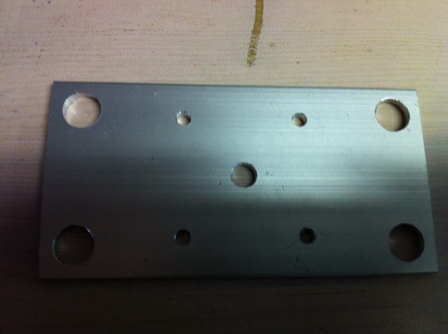
This is the stepper mounting plate. The center hole is for the spindle, the 4 smaller screw holes are for M3 mounting screws for the stepper, the outer holes mount to the top plate of the cutter using well nuts. In an original prototype, the mounting was different, so the outside holes can be reduced in diameter to fit the bolt you're using, as the wellnuts are mounted through the clear top plate:
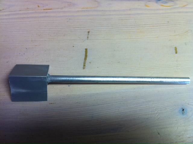
This was a cutter arm design I experimented with to produce an "Angled Cut" (the idea being to cut at the speed of the moving water), however it didn't produce any gain. The design is now flat instead of angled, I'm just providing this so you can get an idea of dimensions and what the arm looks like. It's Aluminimum:

Last edited by jetty on Wed Sep 28, 2011 10:06 am; edited 1 time in total

jetty- Nozzle Novice

- Posts : 60
Join date : 2011-05-07
Location : Toronto, ON, Canada
2 Wire Stepper Motor Driver With Disable
![]() jetty Wed Sep 28, 2011 9:59 am
jetty Wed Sep 28, 2011 9:59 am
However, normally with 4 line driving, you can switch all 4 lines off (the stepper isn't holding), but you're saving power / heat. With 2 line driving this wouldn't work, so, I've created a disable pin circuit. Hold this pin high and the steppers are enabled. To disable, hold low, and hold control pins low.
Normally on hold, the steppers will reach 60C and the drivers around the same, although this is fine, there is excess heat being generated, everything will last longer if you disable the drivers and steppers when not cutting. Provided the cutting mechanism is light enough, the stepper holds even without a holding current being applied.
Credit for 2-Wire Control of UniPolar steppers goes to Sebastian Gassner, and this web page: http://www.tigoe.net/pcomp/code/circuits/motors/stepper-motors
Circuit displayed is for 1 stepper, if you need to control more than one stepper, then increase the fuse (Max Coil Current x # Coils x # Steppers), one fuse can be shared between all the steppers. Also, the 2N3904 transistor and the 4.7K resistor can be shared between multiple steppers so you have one disable pin for multiple steppers, or you can not share if you wish to have an individual disable pin for each stepper.
The temperature sensor (DS18B20) is one of a number of temperature sensors located on a 1-Wire bus using parasitic power. This requires 2 connections, 0V and Data. There is a 4.7K Resistor located at the Arduino that is a pull-up resistor from the Data line to the 5V line, only one is required per bus. The data line is located at Pin 5 on the arduino.
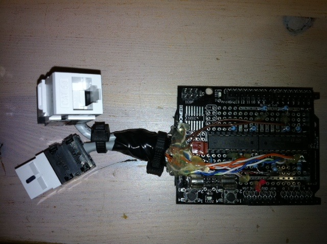
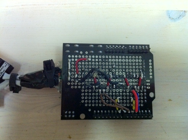
I managed to get 2 stepper motor drivers on to one arduino prototype shield.
Parts List:
Per Stepper:
1 - SY42STH38-0406A Stepper Unipolar
1 - ULN2803A Darlington Array
1 - DS18B20 1-Wire Temp Sensor
4 - 1K Resistor
1 - 1N4007 Diode
Disable Circuit:
1 - 4.7K Resistor
1 - 2N3904 Transistor
Other:
1 - 0.8Amp Fuse and holder (1 stepper, increase for additional steppers)
Schematic (click for full schematic):

Video of it on prototype board:
2 Stepper drivers mounted on Arduino Proto Shield. (copious amounts of hot glue used for strain relief :-) ):
The backside of the board:
jetty- Nozzle Novice
- Posts : 60
Join date : 2011-05-07
Location : Toronto, ON, Canada
Opto isolated remote pump switch (for MicroController)
![]() jetty Wed Sep 28, 2011 10:41 am
jetty Wed Sep 28, 2011 10:41 am
The reason for opto-isolation is for safety reasons. This circuit could be designed with relays (it's cheaper), but I decided to go with an Solid State Relay (SSR) for safety reasons and contact longevity (there are no contacts).
SSR's switch when the current crosses zero, where as a regular relay crosses at any time, so you can get full current and a huge spark which eats away at the contacts causing failure over time. You could create a zero crossing circuit with a regular relay too if you can figure out the delay to switch on the contacts and it was repeatable.
I.E. This is the cadillac of mains switches, but you could do it cheaper than I've done it here.
Disclaimer: This involves mains power, make sure you know what you're doing, don't blame me if you kill yourself :-) Also, make sure you get live / neutral the correct way around, particularly as many pumps don't have an earth. Also, check your electrical codes, this may not be up to your local electrical code standards.
Parts List:
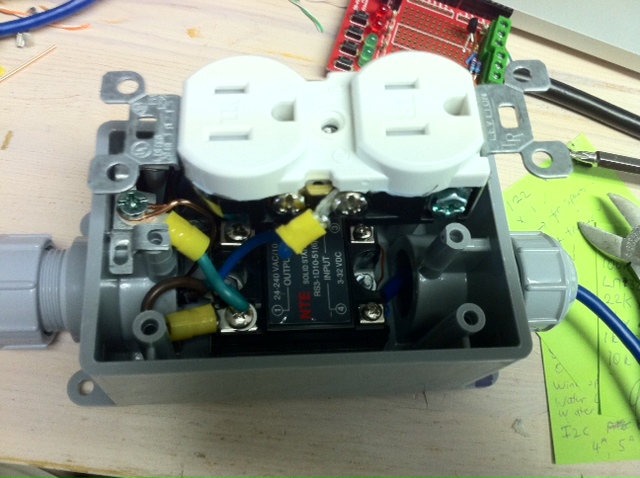
1 x NTE RS3-1D10-51 SSR (10 Amp, DC Controlled) http://nteinc.com/relay_web/pdf/RS3.pdf (110VAC or 240VAC)
1 x Waterproof electrical box
2 x Waterproofing cable gromits
1 x Insulating, fire resistant piece of electrical card
330 Ohm Resistor
Additional Heatsink (earthed) - Optional
I'm running this controlling 2 pumps (4A in total).
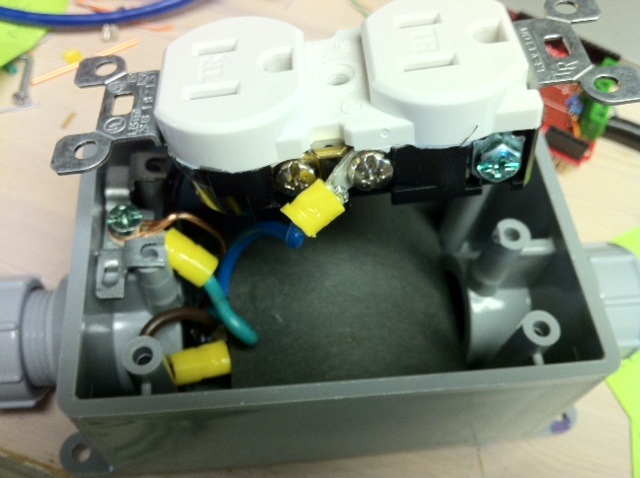
Assembly: It's very important to keep the mains power side and DC side separate from each other. Connections can become disconnected, and you don't want mains power on the DC side for obvious reasons (doubly important as you're using water). For this reason, you will see in the 2nd picture that I've used a bent piece of electrical insulation card to completely cover the SSR. The DC side is hidden under this card. The 330 Ohm Resistor goes on the + DC Line (Screw terminal 3 on the SSR) (you don't want to blow the LED in the Opto Isolator).
Regarding the heatsink, feeding 4 Amps through it didn't change the temperature of the built in heat sink on the base of the SSR, so I didn't couple it to any kind of heat sink. However I did earth (mains power earth - DO NOT tie to the DC 0V) the inbuilt heat sink. If you're planning on running more than 4A through it, you will want to check the temperature of the built in heat sink and see if you need to add an additional heat sink (it's an enclosed box, so temperature could get high).
The rest is obvious, if it isn't obvious to you, then ask a professional to make it for you.
** IMPORTANT: Label the socket 10Amp Max Total, Laminar Jet Pumps Only ** If you think there's a chance others will plug different things into this socket by mistake, you may want to provide a lock over it or secure it with other means.
Showing layout (SSR in the bottom of box):
Showing final assembly (note curved electrical insulating card in place):
Completed:

Last edited by jetty on Thu Sep 29, 2011 2:32 pm; edited 1 time in total
jetty- Nozzle Novice
- Posts : 60
Join date : 2011-05-07
Location : Toronto, ON, Canada
Cutter info.
![]() JohnJarvis Wed Sep 28, 2011 11:57 am
JohnJarvis Wed Sep 28, 2011 11:57 am
JohnJarvis- Nozzle Newbie

- Posts : 24
Join date : 2009-04-17
Re: Jetty's Wifi Web Based Laminar Jet Project
![]() jetty Wed Sep 28, 2011 2:52 pm
jetty Wed Sep 28, 2011 2:52 pm
jetty- Nozzle Novice
- Posts : 60
Join date : 2011-05-07
Location : Toronto, ON, Canada
Solid State Wind Speed Sensor
![]() jetty Fri Sep 30, 2011 8:34 am
jetty Fri Sep 30, 2011 8:34 am
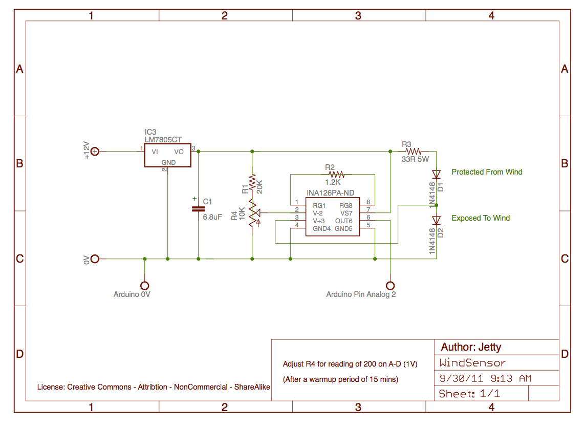
The design heats 2 diodes, one is exposed to the wind and the other is kept protected from the wind. Diodes change their forward voltage according to their temperature in linear fashion (actually you can use them as a cheap temperature sensor when you calibrate them). This design uses this feature, by equally heating both didoes with a relatively high current and measuring the voltage in the center between them.
As the wind speed gets higher, the one exposed to the wind is cooled by the wind, producing a voltage difference at the measuring point. This difference is amplified by an instrumentation amp chip (good quality, low noise) and then fed to the Arduino on Analog Pin 2 for A-D conversion.
Output is non-linear with wind speed, but that doesn't matter as the goal is not get a perfectly accurate measurement, we just want to auto shutdown the jet at a certain windspeed.
Credit for the original design / concept goes to MTM Scientific: http://www.mtmscientific.com/anem.html
I've taken this design and changed a few things. Dropped the Panel Meter and 100K resistor. Increased the 6 Ohm 5W to 33 Ohm 5W to use less current, this makes it less sensitive, but uses significantly less current and the sensitivity isn't that important for our needs. Also replaced the 5V power supply with a slightly different design. The schematic on the website mentions the INA122 and the parts list, the INA126. I ordered both and tried both. The INA126 performed much better, use that.
The sensor is very sensitive to the regulation of the 5V supply voltage. For that reason I didn't use the Arduino on board 5V regulator and maintained the separate regulator for the wind sensor.
When calibrating, set the variable resistor for a reading of 200 (out of 1024) on the A-D input on the Arduino (1V on output). Do this after the sensor has warmed up for 15 mins. The design uses approximately 100mA.
Although the wind sensor works well whilst testing, I haven't had time to write code yet to measure the speed and determine a cut off and we now have laws against driving down the highway calibrating whilst sticking a wind sensor out of the window. I have suspicions that the output is somewhat temperature dependent from the initial testing I did.
So I'm calculating the standard deviation of 20 data points (taken 15 secs apart over the last 5 mins) to get an idea of variability of the wind instead as wind forms gusts and generally it's more gusty the higher the speed is. My plans to calibrate are is to plot the Max, Standard Deviation, Average and Temperature, and readings from my regular roof top weather station in a spreadsheet and figure out the relationship, then figure out what speed the laminar jet is deflected at, and calibrate the wind sensor to shutdown at that minus a little bit. I'll update this thread when I figure that part out. But in the meantime, don't let that detract from you experimenting with it, as the readings I've been getting on my arduino fluctuate more as the wind speed gets higher.
Parts List:
1 - LM7805CT
1 - Heatsink (for LM7850CT)
1 - 6.8uF Capacitor
1 - 10K Trimmer Resistor
1 - 20K Resistor
1 - 1.2K Resistor
1 - 33 Ohm 5 Watt Resistor
2 - 1N4148
1 - INA126PA-ND
Schematic (click to see full):
Diode sensors, the diode on the right is the one exposed to the wind:
Sensor package:
Sensor package + cap:
Electronics (these are housed in a separate case to avoid heating of the sensor due to the 33Ohm resistor):
Completed (electronics on left, sensor on right):
Mounted on Laminar Jet (top left):

jetty- Nozzle Novice
- Posts : 60
Join date : 2011-05-07
Location : Toronto, ON, Canada
Thumper Unit
![]() jetty Fri Sep 30, 2011 9:21 am
jetty Fri Sep 30, 2011 9:21 am
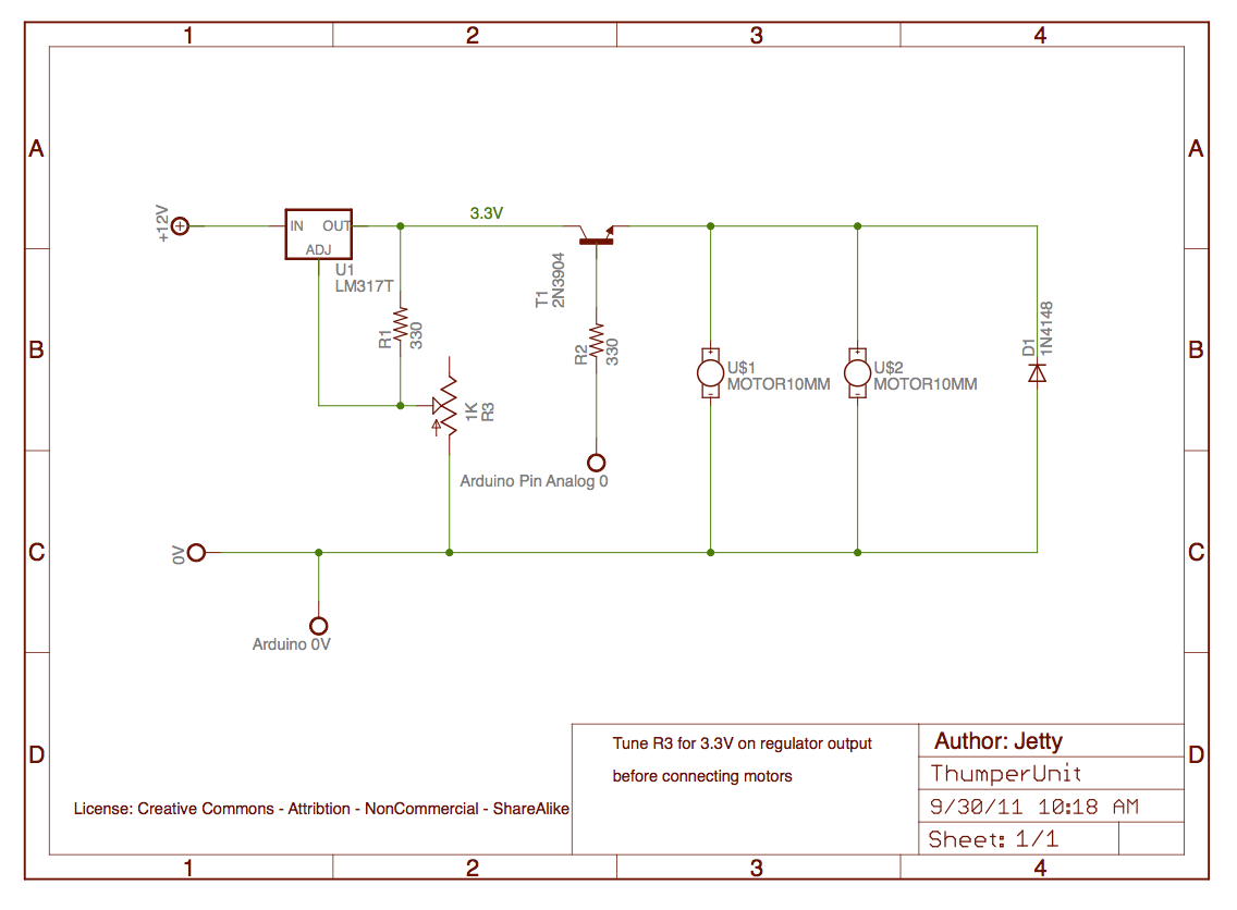
The following is a low power thumper unit for 2 nozzles. Digital high switches on. Total current usage is 110mA with both motors on. Adjust the variable resistor for a 3.3V output at the regulator output before connecting the motors, then adjust again after connecting the motors.
Everything was built on a Arduino Proto Shield.
Parts List:
1 - LM317T
1 - Heatsink (for LM317T)
2 - 330 Ohm Resistor
1 - 1K Trimmer Resistor
1 - 2N3904
1 - 1N4148
2 - Vibration Motors (Source)
Schematic (click for full):
jetty- Nozzle Novice
- Posts : 60
Join date : 2011-05-07
Location : Toronto, ON, Canada
Temperature Sensors
![]() jetty Fri Sep 30, 2011 9:42 am
jetty Fri Sep 30, 2011 9:42 am
I monitor the outside, electronics, stepper motors and led heat sinks (total 6 sensors).
I use the DS18B20 1-Wire Temperature Sensor. The reason for this is because I can put all the temperature sensors on 1 bus, they are individually addressable, and I only have to use one pin on the Arduino to read all the temperature sensors.
Using the parasitic power mode of the temperature sensors, you can get away with just 2 wires to the sensor, GND and Data.
I have the sensors in a star topology (see this warning: http://www.maxim-ic.com/app-notes/index.mvp/id/148 ). It's not recommended, but mainly works (occasionally I get a misread (Value: -127.00) on a temp sensor and have to reread). If you want complete reliability, then make sure it looks like one long bus (but you'll need wires back from the sensors) or use a 1-Wire hub.
The temperature sensors have pin 1(GND) and pin 3(VDD) connected together at the sensor to enable parasitic mode, so you have 2 connections to the sensor pins 1,3 (GND) and pin 2 (Data). There is one pull-up 4.7K resistor at the Arduino that is connected between the pin I'm using for 1 Wire Bus (Pin 5) and 5V.
Outside temperature sensor:
jetty- Nozzle Novice
- Posts : 60
Join date : 2011-05-07
Location : Toronto, ON, Canada
Water Level Sensor
![]() jetty Fri Sep 30, 2011 10:04 am
jetty Fri Sep 30, 2011 10:04 am
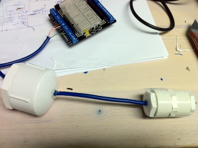
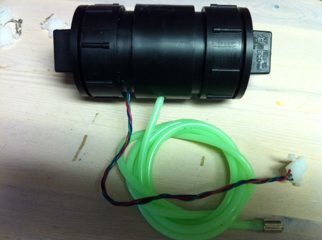
The best solution I found was to use a pressure sensor. The pressure sensor is mounted at the bottom of the tank, and as the tank level rises, the pressure increases.
I have 2 tanks, and they are connected, so you would think only 1 water level sensor is needed as water is self leveling, however I decided to go with 2 sensors, one in each tank as I don't have a lot of water in the tanks and...
As 1 nozzle is firing into the other tank, there will be an imbalance of water because it's doesn't level out immediately.
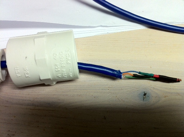
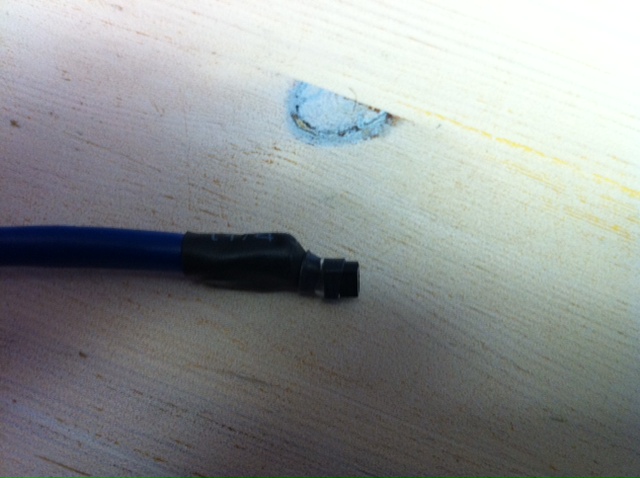
Mounting is relatively easy, I went to the local radio control hobby store and purchased fuel tubing, and a fuel connector with a screw thread on the end. Screwed the fuel connector into a PVC plumbing screw cap which is connected to the bottom of the tank. The electronics need to be at the level of bottom of the tank.
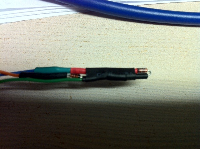
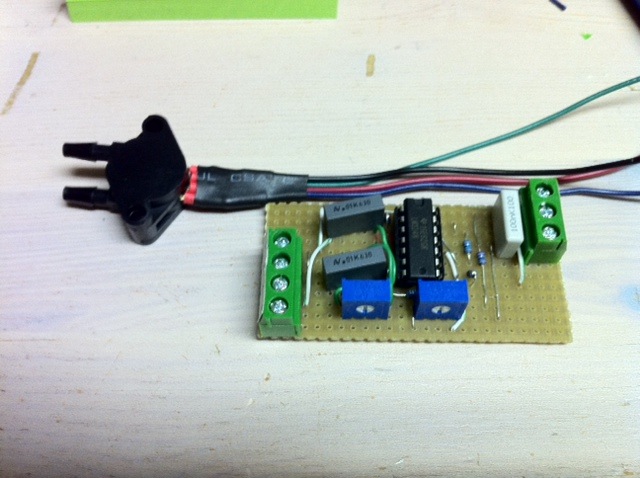
Be careful with the MPX2010DP to wire it up correctly. It's important to use the correct port (the other port should be left open to the air, i.e. don't put it in an air tight container). In the following photos, Pin 1 = Black, 2 = Green, 3 = Red and 4 = Blue.
The project is detailed here: http://www.practicalarduino.com/projects/water-tank-depth-sensor
However what I didn't realize initially until I started to calibrate it and set it up, that it's from a book, and the book contains all the information you need about calibration etc. The book can be purchased:
http://www.amazon.com/Practical-Arduino-Projects-Hardware-Technology/dp/1430224770
It's a good book and also contains a project to pickup from a wireless weather station (which could be useful if you have one and want to read the wind sensor for your jet and want skip having to build one).
Circuit (pressure sensor on top):
Layout (ignore "Clunk" on end of green tube, use a short tube with no clunk):
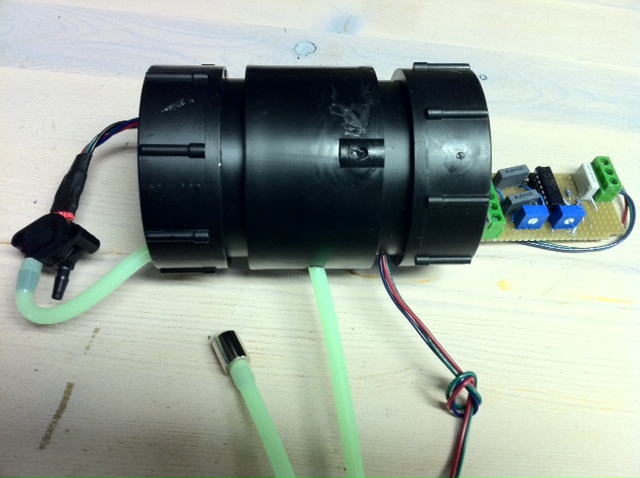
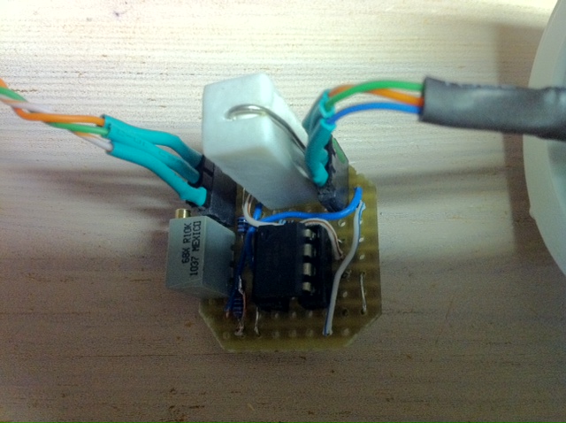
Electronics in housing:

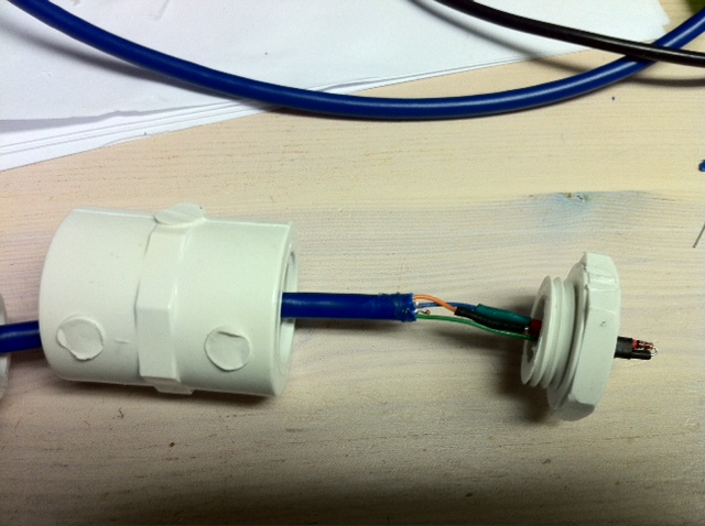
Assembled (ignore "Clunk" on end of green tube, use a short tube with no clunk):
jetty- Nozzle Novice
- Posts : 60
Join date : 2011-05-07
Location : Toronto, ON, Canada
Design Notes
![]() jetty Fri Sep 30, 2011 10:13 am
jetty Fri Sep 30, 2011 10:13 am
The following is for 2 Nozzles, 2 Cutters and 2 Water Level Sensors:
Pin usage on the Arduino Mega 2560 with Linksprite Cupperhead Wifi Shield:
//Pins in use
//D0 Adruino Serial
//D1 Arduino Serial
//D2 CUPPERHEAD WiShield INT0
//D3 Stepper 1
//D4 Stepper 1
//D5 OneWire Bus (Temp Sensors)
//D6 Stepper 2
//D7 Stepper 2
//D8 Pumps
//D9 CUPPERHEAD WiShield successful wireless connection LED
//D10 CUPPERHEAD WiShield Slave Select (SS) Jumpered to D53
//D11 CUPPERHEAD WiShield Master Out, Slave In (MOSI) Jumpered to D51
//D12 CUPPERHEAD WiShield Master In, Slave Out (MISO) Jumpered to D50
//D13 CUPPERHEAD WiShield Clock (SCK) Jumpered to D52
//D48 Stepper Enable
//D50 2560 MEGA - CUPPERHEAD WiShield Master In, Slave Out (MISO) Jumpered to D12
//D51 2560 MEGA - CUPPERHEAD WiShield Master Out, Slave In (MOSI) Jumpered to D11
//D52 2560 MEGA - CUPPERHEAD WiShield Clock (SCK) Jumpered to D13
//D53 2560 MEGA - CUPPERHEAD WiShield Slave Select (SS) Jumpered to D10
//A0 Thumper
//A1 Windspeed
//A2 Water Level 2
//A3 Water Level 1
//A4 BlinkM I2C
//A5 BlinkM I2C
Cupperhead is set to use INT0 (pin2).
Sampling analog sensors can result in incorrect values if the sensors are high impedance as the Arduino has one A-D which is switched between all Analog inputs, so the voltage on the input can take a time to reach the correct value. For this reason, Wind and Water Level Sensors are sampled every 5 seconds, so 1 Wind and 2 Water Sensors will only be sampled every 15 seconds.
Last edited by jetty on Fri Sep 30, 2011 11:57 am; edited 1 time in total
jetty- Nozzle Novice
- Posts : 60
Join date : 2011-05-07
Location : Toronto, ON, Canada
Code Dependencies
![]() jetty Fri Sep 30, 2011 11:32 am
jetty Fri Sep 30, 2011 11:32 am
Here are the libraries and changes that are required for the Arduino Mega 2560 / CupperShield Wifi and the circuits in the above schematics:
- WiShield Wifi Support:
Here's my WiShield fork that adds support for the Arduino Mega 2560: https://github.com/jetty840/WiShield_user_contrib
(Note WiServer calls sendPageURL multiple times to save memory on regular arduinos. The Mega2560 has more memory and multiple calls
can result in occasional corruption due to different sensor values since the last call. A simple page reload repairs the page, but a permanent fix would
be to increase the buffer to be larger than the size of the page, so only one call occurs. The above repository doesn't contain this fix. I'll detail it at some point later.)
- Accelerated Stepper Motor Support:
AccelStepper 1.8: http://www.open.com.au/mikem/arduino/AccelStepper/
- Dallas 1-Wire Temperature Support:
371 Beta (labelled as TCL 3.7.1): http://milesburton.com/Dallas_Temperature_Control_Library
- Free memory monitoring (useful whilst developing):
http://www.arduino.cc/playground/Code/AvailableMemory
- One Wire Support (for Temperature Sensors):
(Version 2.0)
http://www.pjrc.com/teensy/td_libs_OneWire.html
- BlinkM MaxM Support:
http://thingm.com/products/blinkm/quick-start-guide.html (download "Example Code"). Pull out BlinkM_funcs.h from the Arduino examples and put in your project folder.
- Statistics Support (used for Wind Sensor):
http://www.arduino.cc/playground/Main/Statistics (Note file names are incorrect. Save as Statistic.cpp and Statistic.h (not Statistics.cpp and Statistics.h))
- Time Support and Time Alarm Support (needed for various polling functions):
http://www.arduino.cc/playground/Code/Time
Change dtNBR_ALARMS in TimeAlarms.h from 6 to 20.
jetty- Nozzle Novice
- Posts : 60
Join date : 2011-05-07
Location : Toronto, ON, Canada
Laminar Jet Software
![]() jetty Fri Sep 30, 2011 12:02 pm
jetty Fri Sep 30, 2011 12:02 pm
Note that although it supports 2 nozzles, I haven't built the 2nd nozzle yet, so it will need some minor changes at a higher logic level to work with 2 nozzles. I'll update it when I've built the 2nd nozzle.
Additionally the code needs some cleanup and the wind sensor is currently reporting stats until I calibrate it.
Otherwise it works fine with 1 nozzle. Enjoy.
https://github.com/jetty840/Jetty-Laminar-Jet
jetty- Nozzle Novice
- Posts : 60
Join date : 2011-05-07
Location : Toronto, ON, Canada
Re: Jetty's Wifi Web Based Laminar Jet Project
![]() John Sat Oct 01, 2011 9:24 am
John Sat Oct 01, 2011 9:24 am
That is an amazing project and thanks for sharing SO much. I'm going to be adding more to mine someday and will definitely need some electronic support! Thanks for sharing everything!

John- Nozzle Master

- Posts : 450
Join date : 2009-04-03
Age : 46
Location : Utah -

Re: Jetty's Wifi Web Based Laminar Jet Project
![]() jetty Sat Oct 01, 2011 8:22 pm
jetty Sat Oct 01, 2011 8:22 pm
jetty- Nozzle Novice
- Posts : 60
Join date : 2011-05-07
Location : Toronto, ON, Canada
Re: Jetty's Wifi Web Based Laminar Jet Project
![]() liteglow Thu Nov 03, 2011 2:32 pm
liteglow Thu Nov 03, 2011 2:32 pm
Have not been here for a while
But your work is the most impressive I have seen for a long time!!!
I have been to busy with other projects the last 1-2 years :\
But I promise to be back next summer to make my 2 jets up and running !
They work OK, the biggest problem is to have a working cutter.
So the use of a stepper motor is maybe the way to go.
Sadly the only motor I know how to use is a DC motor and my honda VTEC motor lol :-)
So I think when the times come I need help to use a stepper motor.
but this is for sure the best place to start.
Thanx again for all the incredible updates
please continue your work and share your progress
cya later
Filip
Norway

liteglow- Admin
- Posts : 523
Join date : 2009-04-02
Age : 42
Location : Norway -
Re: Jetty's Wifi Web Based Laminar Jet Project
![]() jetty Mon Nov 07, 2011 8:01 am
jetty Mon Nov 07, 2011 8:01 am
Sadly the only motor I know how to use is a DC motor and my honda VTEC motor lol :-)
So I think when the times come I need help to use a stepper motor.
It was my first time using a stepper and it's was a lot less scary than I thought. Using the Darlington array, I found was the simplest / cheapest solution for driving it. From a programming perspective, you just send binary values to it in sequence, i.e. 00, 01, 10, 11, 00, 01, 10, 11 for example, if you want it to go the other direction, then 00, 11, 10, 01, 00, 11, 10, 01.
Each binary number is the next step, you just hit em in sequence.
However I just grabbed an arduino and a software library for steppers, much simpler then.
jetty- Nozzle Novice
- Posts : 60
Join date : 2011-05-07
Location : Toronto, ON, Canada
Re: Jetty's Wifi Web Based Laminar Jet Project
![]() John Wed Nov 09, 2011 1:27 pm
John Wed Nov 09, 2011 1:27 pm
John- Nozzle Master
- Posts : 450
Join date : 2009-04-03
Age : 46
Location : Utah -
Re: Jetty's Wifi Web Based Laminar Jet Project
![]() jetty Wed Nov 09, 2011 1:51 pm
jetty Wed Nov 09, 2011 1:51 pm
Unfortunately it couldn't keep up with the speed needed and ended up needing to run much slower to avoid missing steps, which is why I went back to the darlington array.
Note, this has nothing to do with Easy Stepper (I haven't tried it), it just jogged my memory when John mentioned it.
jetty- Nozzle Novice
- Posts : 60
Join date : 2011-05-07
Location : Toronto, ON, Canada
Re: Jetty's Wifi Web Based Laminar Jet Project
![]() pmolsen Sat Jun 09, 2012 9:14 pm
pmolsen Sat Jun 09, 2012 9:14 pm
Excellent post. Not sure if you are still monitoring this.
I notice that you tried some of my ideas from https://laminar.forumotion.com/t125-designing-the-perfect-cutter but say they didn't make much difference.
I am curious as to how closely you attempted to follow them. I am not criticizing you or promoting my ideas, which are purely theoretical. I am just interested in whether or not they are worth experimenting with further.
1. Speed of the cut.
As I pointed out in my calculations, to achieve a square cut of the stream a rotating cutter slicing through a 1/2" stream at a 60 degree angle has to be rotating at 2000 RPM at the time it starts cutting. If the cutter moves slower than the optimum speed then the entire exercise will be pointless as it will cause the water to spray as it cuts.
If you are using a standard stepper motor starting from a stationary position I believe achieving such a speed (within quarter of a revolution) is impossible. Were you able to do anything to achieve the required speed? I suggested that it would probably require a spring-loaded mechanism, as shown in my YouTube video. I believe that even a normal linear solenoid would struggle to reach the necessary speed.
(The other alternative of course is compressed air. It would achieve the required cutting speed but greatly complicates the logistics.)
2. Razor edge.
I proposed a razor-edged cutter, similar to the razor-edged orifice, not just the blunt edge of a cut sheet of metal. Did you try that? (But pointless if the cutting speed was not high enough.)
3. Cutter angle. (Not the angle that the stream is cut but the angle of the cutter itself with respect to the plane of rotation of the stepper motor).
The diagrams I used explain this point better. See the very first diagram. It shows a long arrow representing the plane of rotation of the blade (the stepper motor shaft would be at right angles to that) together with the blade itself.
The non-leading edge of the blade is tilted back with respect to the plane of rotation, to avoid any surface tension caused by the back end of the cut stream sticking to the surface of the blade.
4. Cutter mounting.
I recommended that the cutter be mounted completely separately from the nozzle to avoid jitter. Did you try that?
pmolsen- Nozzle Newbie
- Posts : 43
Join date : 2009-10-20
Re: Jetty's Wifi Web Based Laminar Jet Project
![]() jetty Sat Jun 09, 2012 9:42 pm
jetty Sat Jun 09, 2012 9:42 pm
have goofed somewhere.
From memory (and it's a while ago now), what I did was the following.
1. Cut Speed. First off I measured the speed of the laminar jet by interrupting it and timing the distance for it
to get to the end taking into account the arc. This gave me a meter/sec speed for the jet which I had to match with the cutter,
To achieve the speed in the stepper I used acceleration so that it would be at the correct speed when the cutter hit the jet.
The cutter formed an arc on a long arm, so that by the time the cutter hit the jet, the speed was matched, therefore the stepper didn't need to reach 2000 rpm, as the longer the arm, the faster the end of it moves when outlining a circle.
The verification of this is that you can also do the same thing water powered (which I did), where a bit like some crazy sprinkler cutter.
Also, because of the long arm, and the small diameter of the jet, the circle cut approaches straight wrt to the jet.
Compressed air I would think would work.
2. Razor edge. I sharpened the cutter to a razor edge. Also tried testing with a semi circle shaped cutter (matching the diameter of the stream).
3. Not sure, it was a while ago, I'll have to think about that one some more.
4. Cutter mounting. I tried both approaches. Holding the cutter manually (i.e. not connected to the tube), didn't solve it.
The above design was simple to prove the concept, mainly on the cut as there was no handling of back cut, and it was one huge cutter and impractical. However if I saw the cutter work effectively on the cut, then I'd have put the work in to implement something smaller.
From memory I think the arm was something in the range of 30cm - 50cm in length. It was Aluminimum with an aluminum cutter and aluminum hub (i.e. lightweight). Not much torque, but awesome to watch flying around.
Out of interest, have you got it to work? Certainly the theory seems sound, and I'd like to use a better cutter implementation is possible.
jetty- Nozzle Novice
- Posts : 60
Join date : 2011-05-07
Location : Toronto, ON, Canada
Re: Jetty's Wifi Web Based Laminar Jet Project
![]() pmolsen Sun Jun 10, 2012 2:01 am
pmolsen Sun Jun 10, 2012 2:01 am
I then set about building a spring-loaded cutter pivoted at one end. Not intended to be the final version, just to test the theory. It was about 10" long with the spring at about 3" so the far end cut super-fast into the stream.
Unfortunately the cutter blade I used was a bit narrow (30mm x 3mm flat aluminium) so the water sprayed around it both sides. I put a video camera on it and then had a close look on my PC afterwards. In amongst the splashes I believe that I saw a clean end to the stream, but I will have to do some more work tomorrow to confirm. I will widen the cutter so I can see the end of the stream clearly to check if it is clean.
To get the angle on the blade I simply twisted the flat strip around its centreline by about 10 degrees, about 3" from the end. I then filed it on the bottom of the leading edge to create the razor edge.
I believe the theory is still sound. I just need to prove it.
The current setup is clearly not suitable for actual installation so I am still not sure that it will help with the final product.
pmolsen- Nozzle Newbie
- Posts : 43
Join date : 2009-10-20
Re: Jetty's Wifi Web Based Laminar Jet Project
![]() pmolsen Wed Jun 13, 2012 11:45 pm
pmolsen Wed Jun 13, 2012 11:45 pm
pmolsen- Nozzle Newbie
- Posts : 43
Join date : 2009-10-20
Page 1 of 2 • 1, 2 ![]()
» Liteglow`s laminar project
» Magic_Nozzle's Laminar Project
» Another laminar project - picture album
» Ike's Prototype Project - My first laminar nozzle
|
|
|