My Project
+14
Atmoz
JohnJarvis
davo
Ike
aususer
Steffen
pbracer
Jerry
Magic-nozzle
mrwebb
Therons
liteglow
John
covewi
18 posters
Page 7 of 10
Page 7 of 10 •  1, 2, 3, 4, 5, 6, 7, 8, 9, 10
 Re: My Project
covewi wrote:Well I had to take the fountain apart tonight - it wasn't the perforated aluminum metal itself that caused the problem - it was the Aluminum Chloride crystals
that formed on the metal. Most likely from the Chlorine in the swimming pool.
This is why we should NEVER use aluminum in our fountains!
https://2img.net/h/oi30.tinypic.com/2s76rk9.jpg
More than 50 % of the holes are clogged.
Will cut a a piece of stainless steel for the bottom plate - adds support for the straws - and will use fiberglass window screening for the top.
Live and let learn.
Wow, this looks Horrible!

Magic-nozzle- Nozzle Grand Master

- Posts : 287
Join date : 2009-04-02
Age : 56
Location : Europe
 Re: My Project
That's good to actually see some results as to why we should avoid using certain metals in the nozzles. You are doing everyone a great big favor!!! Thanks for posting and posting often.
Side note:
When you are "finished" with you nozzles do a final post/video and I will change your title to "NOZZLE GRAND MASTER" like Mario's title. That title can only be earn by someone who have completed their nozzle project, and contributed a lot to the forum (which have already done).
Side note:
When you are "finished" with you nozzles do a final post/video and I will change your title to "NOZZLE GRAND MASTER" like Mario's title. That title can only be earn by someone who have completed their nozzle project, and contributed a lot to the forum (which have already done).
 Re: My Project
John - Thanks.
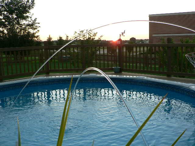
Will do. Here is the first photos of both fountains going.
Wow what a difference without the blockage.
If the wind dies down I hope to have some nice photos and videos later today.
The fountain on the right has light - the other will have to wait till next year. I want to sit back and enjoy
this for now.

Videos
View My Video
View My Video
Will do. Here is the first photos of both fountains going.
Wow what a difference without the blockage.
If the wind dies down I hope to have some nice photos and videos later today.
The fountain on the right has light - the other will have to wait till next year. I want to sit back and enjoy
this for now.

Videos
View My Video
View My Video
covewi- Nozzle Pro

- Posts : 248
Join date : 2009-06-07
 Re: My Project
Found this video on youtube about Mark Fueller.
https://www.youtube.com/watch?v=FoL5GunGaeY
https://www.youtube.com/watch?v=FoL5GunGaeY
covewi- Nozzle Pro

- Posts : 248
Join date : 2009-06-07
 Re: My Project
covewi wrote:Found this video on youtube about Mark Fueller.
https://www.youtube.com/watch?v=FoL5GunGaeY
Ohh thats a nice video, thank you for the link. Your Fountain looks really nice, good work. If you put the Nozzles in the ground, then it is a perfect setup, do you plan to do that? It looks also nice like this, but the magic is happen if you dont see the Nozzles, just the perfect stream.
Regards Mario

Magic-nozzle- Nozzle Grand Master

- Posts : 287
Join date : 2009-04-02
Age : 56
Location : Europe
 Re: My Project
Would love to do that but the cross members from the deck are right below. It would take a great deal of deck rebuilding to make it work.
My idea was to build some sort of rock garden-wall around and between both and using plants to hide everything.
What do you think?
My idea was to build some sort of rock garden-wall around and between both and using plants to hide everything.
What do you think?
covewi- Nozzle Pro

- Posts : 248
Join date : 2009-06-07
 Re: My Project
covewi wrote:Would love to do that but the cross members from the deck are right below. It would take a great deal of deck rebuilding to make it work.
My idea was to build some sort of rock garden-wall around and between both and using plants to hide everything.
What do you think?
Ohh Yes. this sounds good, also a box of the same wood like the deck will be fine, better than a not real looking rock.

Magic-nozzle- Nozzle Grand Master

- Posts : 287
Join date : 2009-04-02
Age : 56
Location : Europe
 Re: My Project
Yes - have four solenoids but that's as far as I have gotten.
Design ideas?
Design ideas?
covewi- Nozzle Pro

- Posts : 248
Join date : 2009-06-07
 Re: My Project
I shortened up some tubing, rebuilt my low pass filter, and made sure all the air was bleed out of the system -
I am happy now.

This view is with one fountains turning all the way down. The large stream is around 12 in length and 5 feet high.

Next up 40 Watt LED's from www.ledengin.com - they are brand new.
You can get 40 watt white, 40 watt rgb, 40 watt rgb(ambler), 40 watt rgb(white).
What would be the a good voltage to run all three colors at? I already have the constant 700 ma source built.
http://ledengin.com/ledengin_products-dataLZ.htm
http://ledengin.com/products/40wLZ/LZC-00MC40.pdf
Got to try one - ordered a 40 watt rgb today.
I am happy now.

This view is with one fountains turning all the way down. The large stream is around 12 in length and 5 feet high.

Next up 40 Watt LED's from www.ledengin.com - they are brand new.
You can get 40 watt white, 40 watt rgb, 40 watt rgb(ambler), 40 watt rgb(white).
What would be the a good voltage to run all three colors at? I already have the constant 700 ma source built.
http://ledengin.com/ledengin_products-dataLZ.htm
http://ledengin.com/products/40wLZ/LZC-00MC40.pdf
Got to try one - ordered a 40 watt rgb today.
covewi- Nozzle Pro

- Posts : 248
Join date : 2009-06-07
 Re: My Project
According to the spec sheets it is still the 700mA that is the recommended supply current, but you have to supply ~9V for red, ~14V for blue, and ~17V for blue! Since you are spending quite a bit of money on this, I'm just going to warn you (as I'm sure you already know) the 5W tell you not to operate these without proper heatsinks, this is 8X as worse. Make sure you take all the precautions to heatsink this properly, make sure you use some thermal grease or something to help the conduction to your heatsinks!
I'm so excited to see that!!!!
I'm so excited to see that!!!!
 Re: My Project
If I remember from previous discussion's the voltage does not matter as much as the proper amps.
Could I run all three colors around 14 - 15 volts as long as the ma's are 700 and a proper heat sink with fan is used?
Otherwise I need to run three separate voltages - big pain!
I guess I could control the voltage out of each color?
From this specs -
Minimum
4 Red 4 Green 4 Blue
0 8.96 14.72 12.80
Maximum
4 Red 4 Green 4 Blue
12.80 20.48 16.64
covewi- Nozzle Pro

- Posts : 248
Join date : 2009-06-07
 Re: My Project
Hopefully Ike will pipe in soon, but you are right you only need to supply the correct current, but you need to have enough power to supply the correct volts to all of them. So essentially you will need a 50V power supply for one LED. LOL That is going to be awesome.
 Re: My Project
I am still learning but dont think I will need that much voltage. Only have to make sure that I supply more than enough amp's.
I am now running a 9 volt 2.7 amp power supply for my 5 watt led's that require between 7-9 volts and 700 ma's.
700 ma times 3 = 2.1 amps. That's all I was worried about.
If I ran each color of the 40 watt led at 24 volts that should cover them all. I dont think the voltage needs to be added up to total the needs
of each color. I may be wrong.
I could then regulate the voltage down to the needs of each led.
Thoughts?
covewi- Nozzle Pro

- Posts : 248
Join date : 2009-06-07
 Re: My Project
Oh, yeah, I got mixed up. You are right you will need a power supply that can handle 36 amps 2.1 amps at 20+ volts.
Last edited by John on Wed Jul 14, 2010 8:29 am; edited 1 time in total
 Re: My Project
I suppose you could just build 24 current regulators, one for each LED and then keep the same voltage you have... LOL
Assuming you're sane and set all 4 LEDs of each color in series then you're going to need a 24V power supply to give you enough head room (18V won't be enough when factoring in misc losses and its hard to find any reasonably priced supplies between 18 and 24v).
The problem is going to be heat in your LM317s if you go straight off of the 24V. Basically what a LM317 current regulator circuit does is vary the voltage output to keep the same current. That means its going to eat the extra voltage it has to cut off between your supply voltage and your LED voltage drop. To find the heat dissipation you take the supply voltage minus the LED V drop times your current supply.
Heat dissipation for your LM317s (VI=P):
Greens (16.8V Drop) --> (24V-16.8V)*.7A = 5.04W
Blue (14V Drop) --> (24V-14V)*.7A = 7W
Red (9.4) --> (24V-9.4V)*.7A = 10.22W
So as long as you have a heat sink big enough to handle 10W of heat dissipation at whatever your ambient temperature is you should be good to run it off of a 24V 3A supply. Also keep in mind you'll have a LOT more heat in your LED itself. Your big heatsink might work great, if not I suggest a CPU cooler from newegg.com
Ike- Nozzle Novice

- Posts : 74
Join date : 2010-05-03
Age : 40
Location : Wyoming
 Re: My Project
I'm assuming he's going to have a separate lm317 circuit for each color with its own heat sink.
If you use one heat sink for all three LM317s then you're right, you'd have 22W on the one heatsink.
If you use one heat sink for all three LM317s then you're right, you'd have 22W on the one heatsink.
Ike- Nozzle Novice

- Posts : 74
Join date : 2010-05-03
Age : 40
Location : Wyoming
 Re: My Project
How do you size the power supply accordingly. We know that you need 24V. I'm just getting mixed up with the amps, and watts. I'm assuming he is going to have the 3 channels for the Red, green, and blue. So each channel can have .7A. So the power supply needs to be able to supply .7*3=2.1 amps?
So 24V at 2.1 amps? Then select one that can supply a little bit more amps?
So 24V at 2.1 amps? Then select one that can supply a little bit more amps?
 Re: My Project
Pretty much. Just find your required voltage, add up your current draws for all components, and then add some headroom to the current requirement.
When picking a power supply I would say that you should never plan to use more than 75% of its maximum capacity. Reasons being:
1) There are always anomalous voltage drops and resistances in a system for which you need some headroom
2) The closer a power supply gets to its maximum current rating the more fluctuations you tend to get in its output voltage (especially cheaper ones like we tend to use)
When I design systems for precision sensors at work I make sure that my 24V power supplies are never more than 50% loaded to guarantee a smooth output.
So 3 LED strings @ .7A = (.7 + .7 + .7) = 2.1A
2.1A / 75% = 2.8A minimum power supply rating
2.1A / 50% = 4.2A if you want to be thorough and picky
And just FYI for those trying to figure out what power supply to get:
If you want to get into another level of detail with power supplies you can talk about switching versus linear. The difference is how it changes the power from AC to DC. Switching supplies are cheaper and generally have a higher amperage rating at the cost of having a "noisier" output voltage. Linear are more expensive and have smaller amp ratings but have a much cleaner output.
For our use, switching works just fine since the noise is usually at small enough levels that the lm317s will clean it up well enough for you not to notice anything. Plus they're affordable and easy to come by.
Ike- Nozzle Novice

- Posts : 74
Join date : 2010-05-03
Age : 40
Location : Wyoming
 Re: My Project
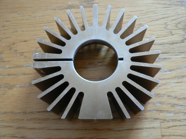
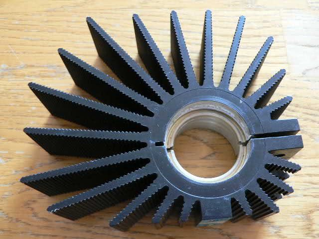
Here's the heatsink that I plan to use for the LED itself - it measures 3" in dia and 1 inch thick - I hope to mount it inside a piece of PVC tubing and directly attach
the LED to the bottom of the plexiglass light stick. Yes the heatsinks will be covered in aluminum.

My choice for the LM 317's is this - it measures 4 " in dia and 1.25 inches thick - add a fan a good to go - thoughts?

the LED to the bottom of the plexiglass light stick. Yes the heatsinks will be covered in aluminum.

My choice for the LM 317's is this - it measures 4 " in dia and 1.25 inches thick - add a fan a good to go - thoughts?

covewi- Nozzle Pro

- Posts : 248
Join date : 2009-06-07
 Re: My Project
I'm no expert on Heat Sinks to be sure, but it almost seems like a computer CPU cooler might be more efficient cooling wise. There are a lot of variables that go into heat conduction and radiation. The only thing that worries me with those heat sinks is how good of a thermally conductive attachment can you make between the components through the aluminum sheet they sit on and into the heat sink itself. A CPU cooler has all of its fins in one solid chunk that come together in a centralized location to guarantee maximum heat conduction away from the attached object.
Then again, maybe the heat sinks you have are big enough not to have to worry about conduction through weld points.
Then again, maybe the heat sinks you have are big enough not to have to worry about conduction through weld points.
Ike- Nozzle Novice

- Posts : 74
Join date : 2010-05-03
Age : 40
Location : Wyoming
 Re: My Project
why not use water cooling ?
There is much water to take from
Use a copper mount on the back of the LEDs, and lead the copper out into the cold circulating water from the nozzle ?
just a idea in my head :-)
There is much water to take from
Use a copper mount on the back of the LEDs, and lead the copper out into the cold circulating water from the nozzle ?
just a idea in my head :-)
 Re: My Project
These came from a halogen fiberoptic light source bulb. Will give them a try - I spoke with a rep from LEDENGIN ( the led manufacturer) yesterday.
He told me that the heatsink was very important and that as long as I could touch the heatsink (right next to the led) for several seconds it should be okay.
I am using a similar setup for my 5 watt led's and the heatsink is cool - with the fan running.
We will see. Thanks. Hopefully next week we will see a test.
covewi- Nozzle Pro

- Posts : 248
Join date : 2009-06-07
Page 7 of 10 •  1, 2, 3, 4, 5, 6, 7, 8, 9, 10
 Similar topics
» upgrade from 3" to 5"
» NEW PROJECT TIME
» my nozzle project
» A Minnesota project
» My project build thread...
» NEW PROJECT TIME
» my nozzle project
» A Minnesota project
» My project build thread...
Page 7 of 10
Permissions in this forum:
You cannot reply to topics in this forum


